
|
COEN
180
|
| Optical Storage |

Figure 1: Cross Section Through a CD
![]()
Figure 2: Geometry of CD disk layout.
The size of the pit and land areas does not change as data are placed on the track, rather, the CD reader adjusts the rotation speed as it moves along the track.
| CD-ROM_Characteristic | Value |
| Disk outside diameter | 120 mm ±0.3 mm |
| Hole diameter | 15.00mm+0.1mm |
| Thickness | 1.2mm±0.1mm |
| Width of data pits | 0.50 um±0.05um |
| Length of data pits | 0.83 to 3.56um |
| Height of data pits | .125um |
| Spiral Track Separation | 1.6±0.1u]m |
![]()
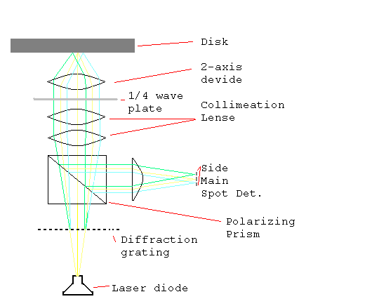
Figure 3: Laser focused on Land / Pit.
Any optical device uses changes in the reflectivity of a medium in order to store data. A laser beam is focused on the medium and a photo sensor measures the amount of reflected light. Figure 3 gives a schematic of an optical read head which uses three beams. A laser diode creates a laser beam. The laser beam is diffracted into a number of diffraction orders. The order zero is used to read the track, the next orders are used for the positioning of the head. Thus - contrary what Figure 3 indicates, three different beams pass through the system. After the diffraction grating, the three different beams pass through a polarizing prism. The vertically polarized portion of the light beams passes through the prism. The quarter wave plate changes the polarization by 45o. Eventually the light beams strike the disk surface and mostly go through to the aluminum reflection surface of the CD-ROM_that carries the data. The two side beams are used to position the optical system over the track. The main beam is used to read the data. After reflection, the light beams pass again to the l/4 plate, where they are rotated another 45o. When they pass through the prism, they are now diverted into the photo-detection system.

Figure 4: A Three-Beam CD-ROM_Optical Head.
Figure 4 shows how the photo-detection system uses the main and the side spots for focusing and tracking. The main sensor is divided into four sectors. The sum of the signal emanating from the four sectors of the main sensor is the radio frequency data signal that carries the data. If the laser is unfocused, then the focus error signal is significant.

Figure 5: Detector System for the Three Beam Optical Head.
Finally, the difference between the side detectors give the tracking signal. The side spots are focused on the track as shown in Figure 6. If everything is fine, then the main portion of the laser is focused on the track, (Figure 6 center), if not, then one or the other of the side beams focuses on the track as well.
![]()
Figure 6: Mistracking (left and right) vs. Correct Tracking on the CD-ROM_for the Three-Beam
Optical Head.
Table 2 gives the outline of a data block in one disk standard. The blocks are not physically separated, but the synchronization bytes allow the system to distinguish the beginning of a new block. The header contains the block metadata. Error detection and error correction are separated. This is done for reasons of speed. (The CD-ROM_standards accomodated the ECC chips of the eighties.) Typically, not every block is in error. Buffering blocks allows us to correct an error while error free blocks are read from the CD and moved into buffer. Errors on a CD stem mostly from media defects such as scratches. These can take out long bursts of data. By interleaving data (that is, by permuting the data bytes) we can limit the amount of errors that continguous pieces of the data stream have in them. For Audio-CDs, we can then interpolate blocks in error.
| Designation | Size | Byte Numbers |
| Synchronization | 12B | 0-11 |
| Header | 4B | 12-15 |
| User Data | 2048B | 16-2063 |
| Error Detection | 4B | 2064-2067 |
| Space | 8B | 2068-2075 |
| Error Correction | 276B | 2076-2351 |
Table 2: ECMA-130 Media Standard for Block Layout
In principle, binary data is encoded as pits for a 0 and as land for a 1. Long pits and lands can be hard to read. The data bit stream is encoded with the EFM code. EFM means eight to fourteen modulation and encodes a byte stream into code words of length 14 bits that consists of single ones separated by two to nine zeroes. For example, the byte 0000 1010 is encoded as 1001 0001 0000 00. The pits thus range in length from 3 bits to 11 bits.
Depending on the use and on the technology at the time of proposal, CDs are subject to a plethora of standards, given in Table 3.
| Physical Format | ||
| CD-Audio | ICE 908 | Red Book |
| CD-ROM | ISO/IEC 10149 | Yellow Book |
| CD-I | Green Book | |
| Video CD | White Book | |
| CD-recordable | ISO/IEC 11172/1/2/3 | Orange Book |
| Logical Format | ||
| CD-ROM | ISO-9660 | High Sierra |
| CD-Recordable | ECMA 168 / IS 13940 | Frankfurt Proposal |

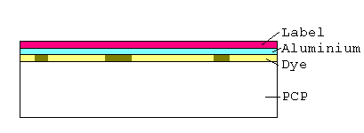
Figure 7:CD R Cross Section.
CD-R disks (Figure 7) have a layer of dye over the reflecting aluminium layer. The dye is photo-sensitive. In normal state, the dye is translucent, but after heating at a given frequency of light, the dye turns opaque, allowing us to store the data. A CD-R optical heat needs two laser light sources, to generate the write and the less intense read light. A CD-R disk has grooves pressed in to enable tracking with the read laser.

Figure 8:CD RW Cross Section.
CD-RW need to be able to erase, i.e. to undo the effect of a write. This is done by using phase shift compounds that have at least two phases of different reflectivity. The compound used in todays CD-RW is a compound of silver, antimony, tellurium, and indium. It melts at 600 o C, and if it cools rapidly, it remains in a fluid, amorphous state that is quite opaque. If however the cooling is slower, then the compound cristallizes into a quite translucent form at around 200oC. The read layer in a CD-RW burner has not enough power to melt the compound. The higher power erase layer can heat the compound to the cristallization point and restore the original cristallization of the compound.
DVDs use the same basic technology as do CD-ROMs, but achieve a much higher (up to seven times) data capacity. DVDs can use double layering, where there are two reflective layers on a single surface. The inner one is made of aluminium (as for CD-ROM), the outer one is a semi-reflective gold layer through which the laser can focus on the inner layer. To achieve the maximum data capacity of 17GB, DVDs can be in a double sided, double layered format, where a total of four surfaces stores data.
DVDs achieve higher data density per layer by halfing the dimensions of the pits / bumps on a CD: the track pitch is 740nm as opposed to 1600 nm, the minimum pit length is 400 nm (440 nm on a double layer DVD) as opposed to 830 nm. Since data is stored on a surface, this effectively quadruples the data density. This reflects the use of higher frequency light with a wave length of 640 nm as opposed to 780 nm for the laser used in CD-ROM.
The error correction scheme on a DVD is much more sophisticated and powerfull than the one used for the CD-ROM standards, reflecting the progress in the theory of ECC, but even more the progress in the processing of data.
Since optical storage densities is limited by the wavelength of the light used, and since moving far from the visible spectrum becomes to costly, optical storage density is limited and hence is no longer the technology of the future for mass storage applications. However, optical storage uses resilient media and has carved out an application domain of archival storage and content distribution through physical carriers. In both areas, we can expect alternative solutions with the perfection of internet trade and the growing capacity of non-volatile electronic memory.
| © 2004 Thomas Schwarz, S.J., COEN, SCU SCU COEN T. Schwarz COEN_180 |