The Drawdio kit is pretty simple compared to most electronic projects.
We will go through it one section at a time, please refer to the schematic
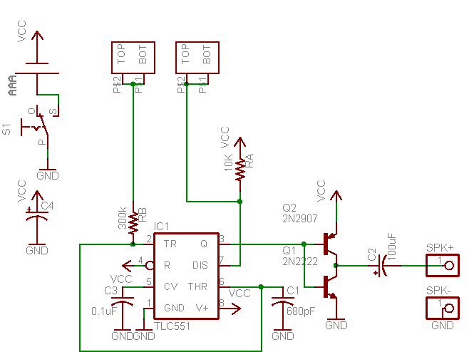
The first part to understand is the power supply, which keeps everything running. The power source is a single AAA battery which is held in a plastic container that is soldered to the PCB. There is also a switch S1 which can connect or disconnect the battery from the rest of the circuit. Finally there is a large electrolytic capacitor C4, which is used as a 'bypass capacitor'. This means that it goes across the AAA battery and smooths out any ripples that are caused from power surges (like when the drawdio makes noise!)
The heart of the kit is a TLC551 chip, which is a low voltage version of the famous LM555 timer chip. This integrated circuit is specifically designed for creating timers and oscillators. The original LM555 needs at least 5V to run (which is more than 3 1.5 batteries!) so we are using the 551 which can run as low as 1V. Its a little more expensive but makes the whole thing fit on a pencil.
One of the more popular ways that '555s are used is as a 'mono stable multivibrator' which is anothe way of saying an oscillator. The frequency of the oscillation is set by 2 resistors and a capacitor. The chip slowly feeds current into the capacitor until it is full and then, likewise, slowly drains it out. The resistors set how fast to fill and drain the capacitor and the size of the capacitor indicates how long it takes before it fills.
This system is pretty much identical to Japanese water fountains, as this video shows:
Except its all with electrons instead of water molecules and capacitor C1 is the 'bucket'. The water fountain oscillates maybe once a minute (1/60 Hz). But electrons are so much faster, a '555 can oscillate at thousands of Hertz, which means it can make audible sound. (Human hearing tends to range from 20Hz to 20000 Hz)
f = 1.44 /(C3 * (RA + 2 * RB))
C3 = 680 pF = 0.00000000068 F
RA = 10000 ohms
RB = 300000 ohm to 1000000 ohm (1 Mohm)
In this case, we use two resistors RA and RB but also have an 'open connection': two tabs at the end of the PCB. If the two tabs are shorted with a piece of wire, then the frequency of the oscillation is 3500 Hz, if instead there is a resistor of 1 Megaohms between the two tabs, the frequency of oscillation is about 1000 Hz. You can use a calculator to do the math yourself using the formula above
Instead of a 'everyday' resistor between the tabs, however, we use something else - the conductivity of the human body and graphite! The human body has a resistance similar to a 200,000 ohm resistor. Graphite has resistance of about 1 ohm per inch when its in the form of a pencil lead. When its spread out on a piece of paper, the resistance goes up a lot, up to a megaohm for a few inches of 'drawn resistor'
The 551 can create audio-frequency oscillations but it is not powerful enough to play them on a speaker, just like an MP3 player needs an amp to play music on large speakers. That's because the 551 was designed mostly for digital logic, not for low impedence (8 ohm) audio outputs. So we will use a Class B 'pushpull' amplfier, which uses two seperate transistors to amplify the sound.
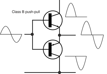
This is pretty much the same thing in your stereo, except your stereo has enormous transistors with gigantic heatsinks so that it can drive large speakers.