These instructions are for the newer v1.1 kit with a thinner PCB and slightly different components. It makes minor upgrades to the kit which reduce power usage. If the photos don't match up, you probably have a v1.0 kit and you should follow the instructions here!
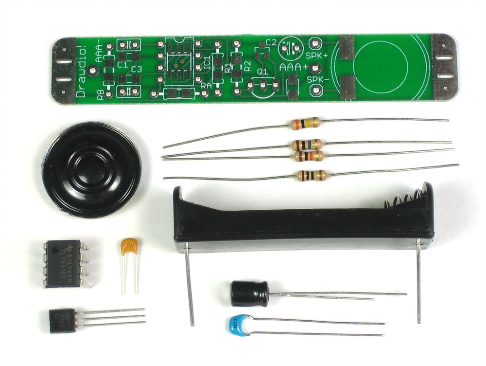 |
Make sure you have all the parts necessary. Check the BOM for a list of everything in the kit. These instructions are for the newer v1.1 kit with a thinner PCB and slightly different components. It makes minor upgrades to the kit which reduce power usage. If the photos don't match up, you probably have a v1.0 kit and you should follow the instructions here! |
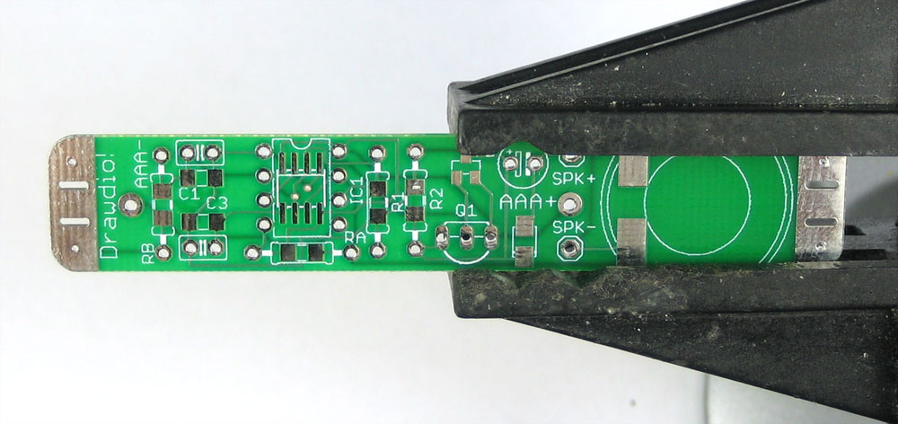 |
Get ready by placing the PCB in a vise Heat up your soldering iron to 700deg F, clean the tip and make sure your sponge is wet Lets go! |
|
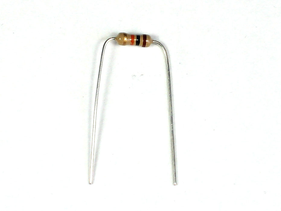
First thing we will place is RA, a 10K resistor (brown, black, orange gold). Bend the resistor into a staple as shown, and slip it in. |
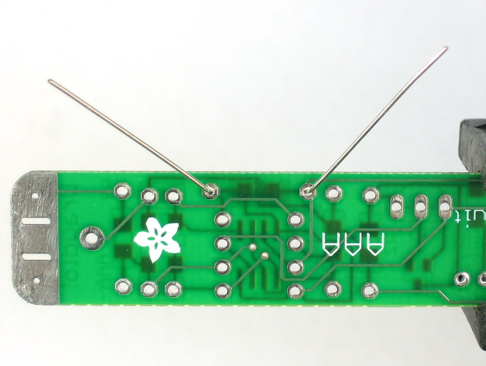 |
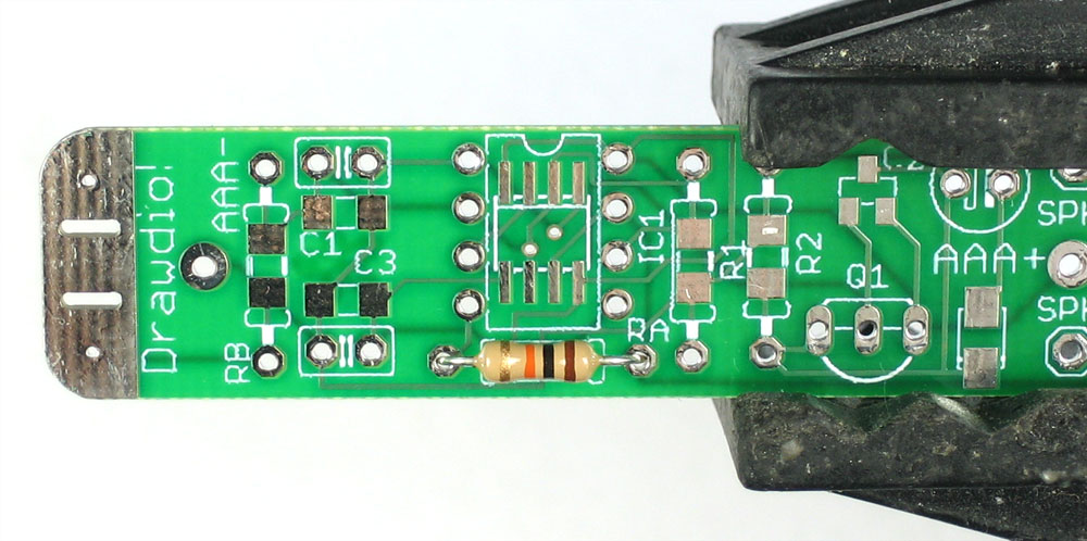
Place the resistor in the location marked RA. Resistors do not have polarity
which means you can put it in 'either way' and it will work just fine.
Bend the wire legs out so that the resistor sits flat against the PCB. |
|
|
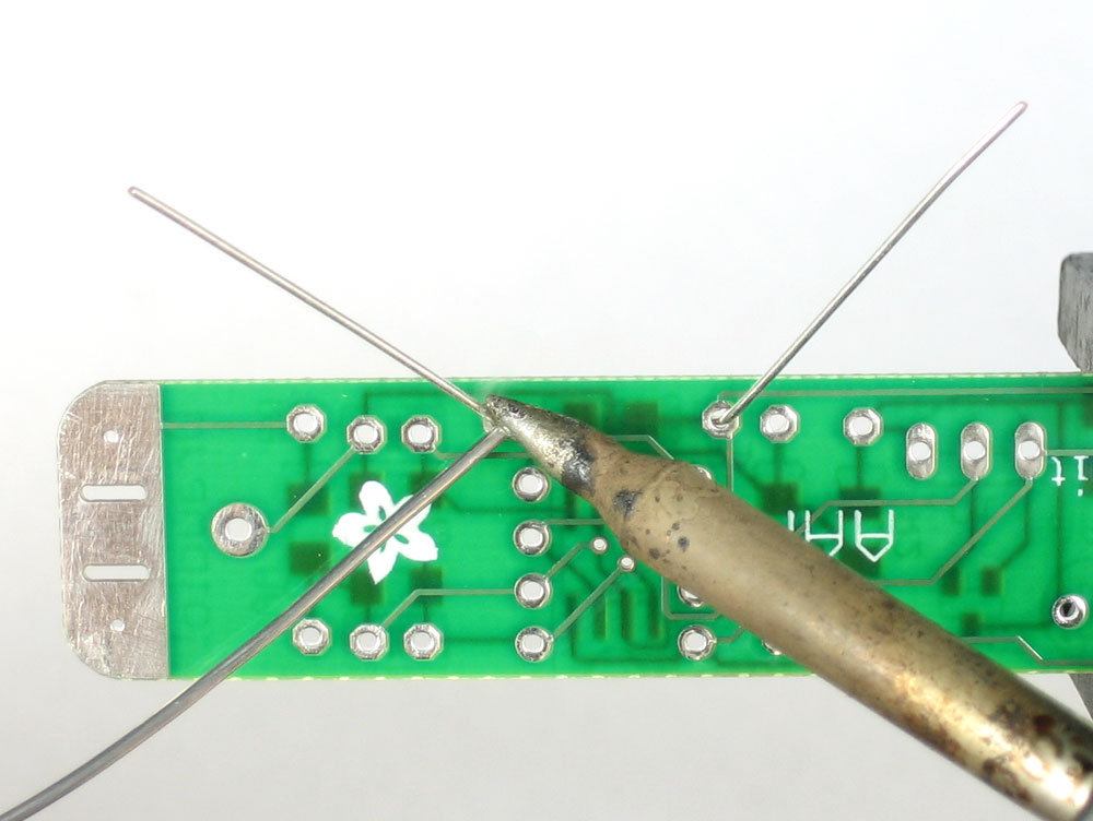
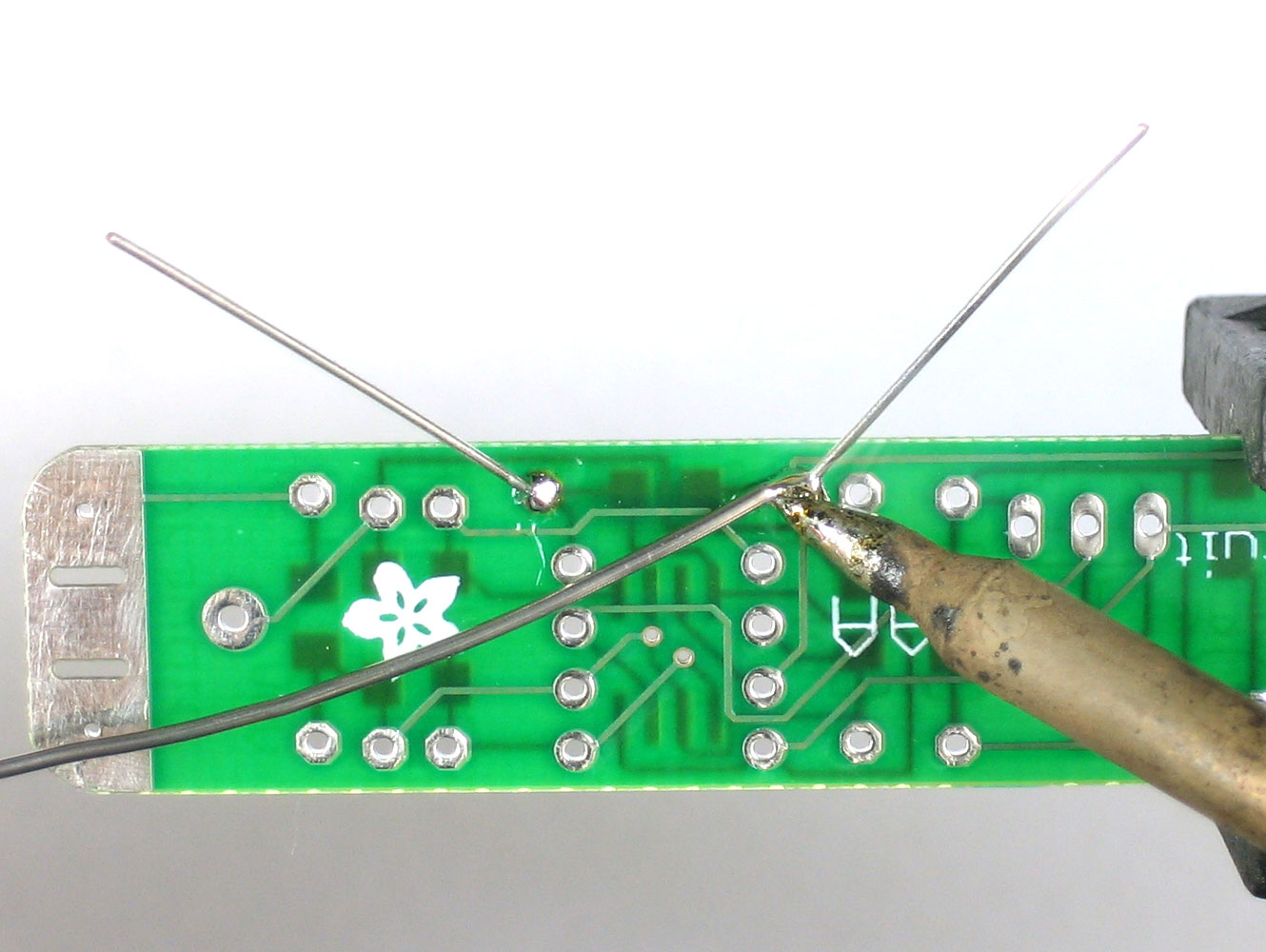
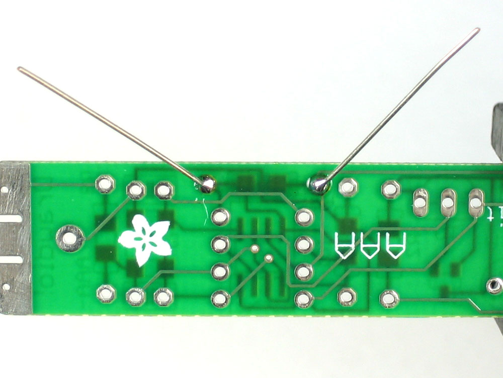
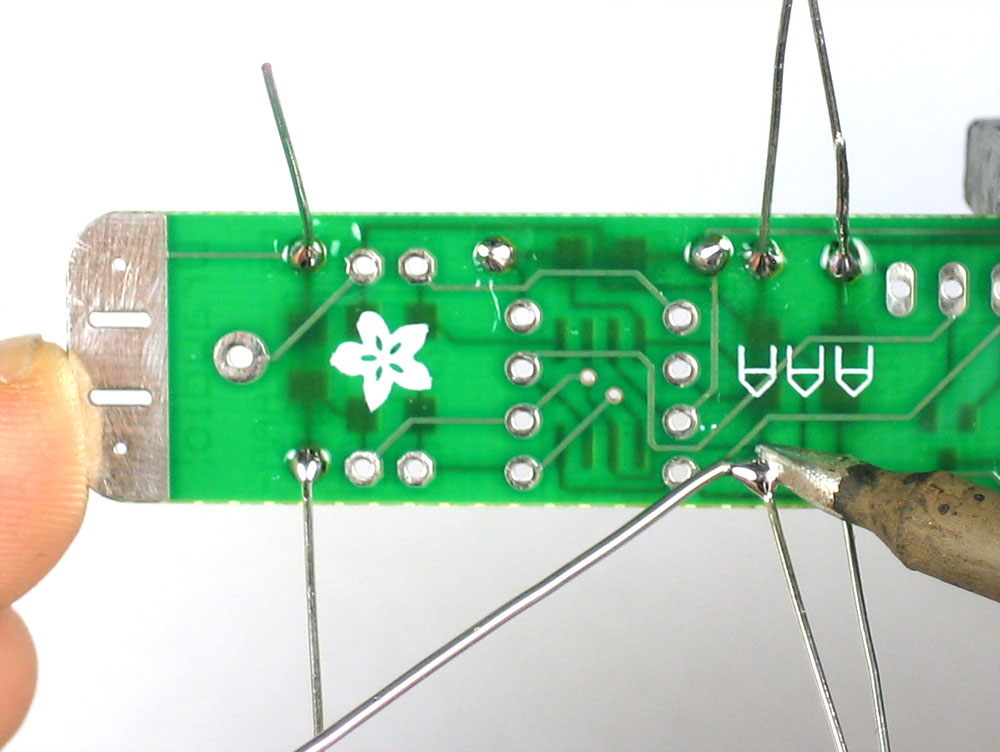
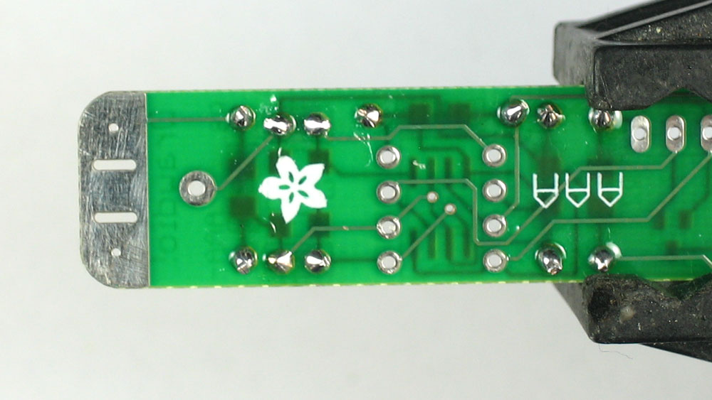
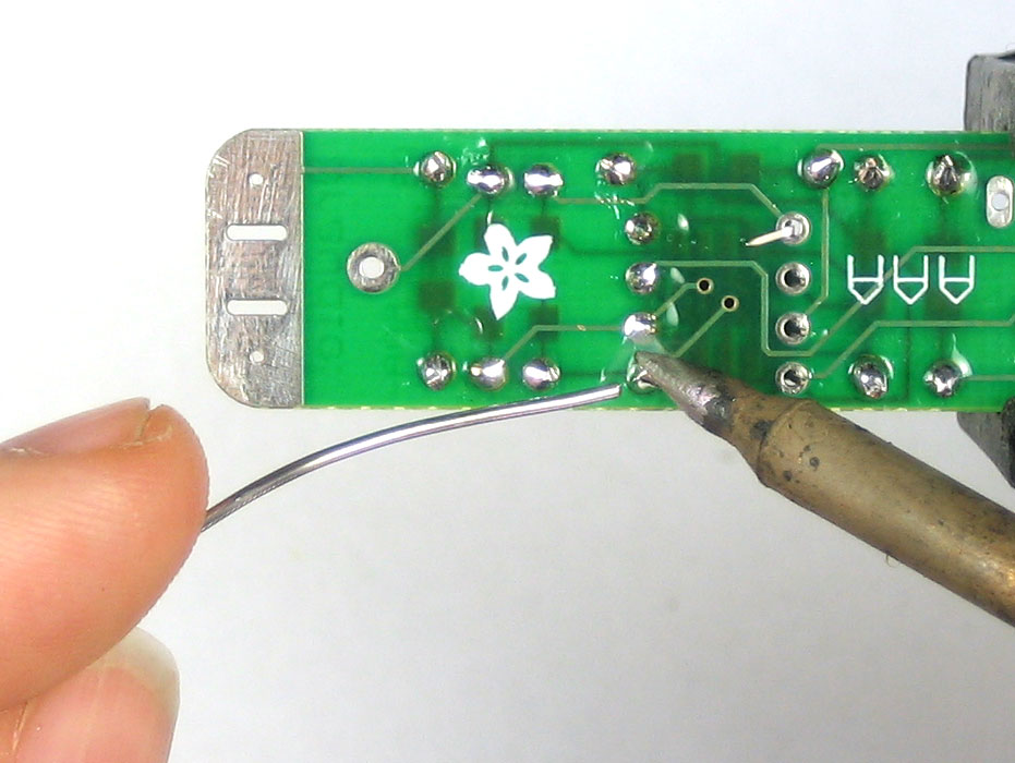
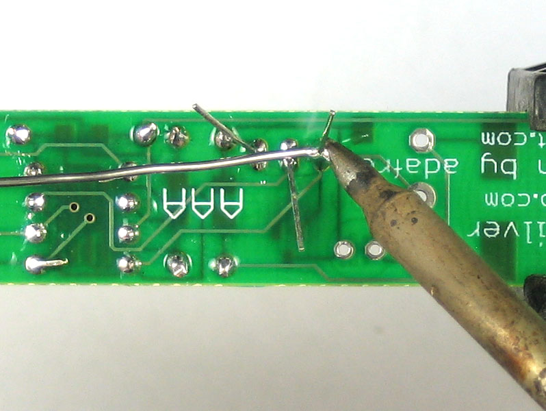
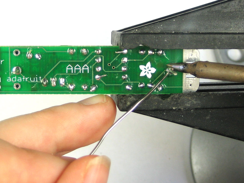
Turn the PCB over. Using your soldering iron tip, press and heat both the pad (the silver ring around the hole) and lead (wire) at the same time for 2 or 3 seconds. Then poke the end of the solder in to create a nice solder joint. Do this for both leads. |
|
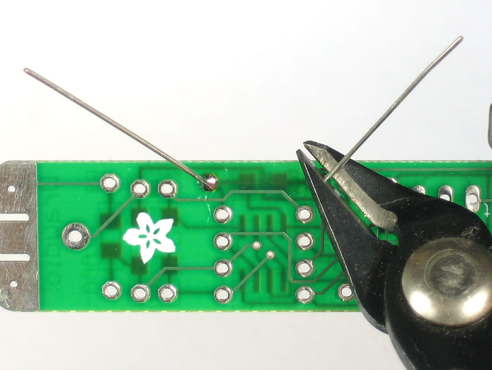
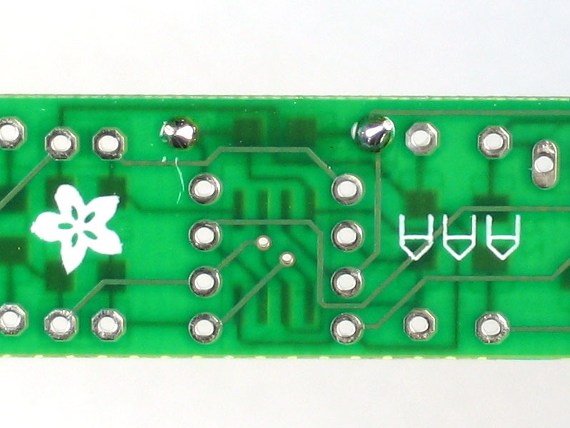
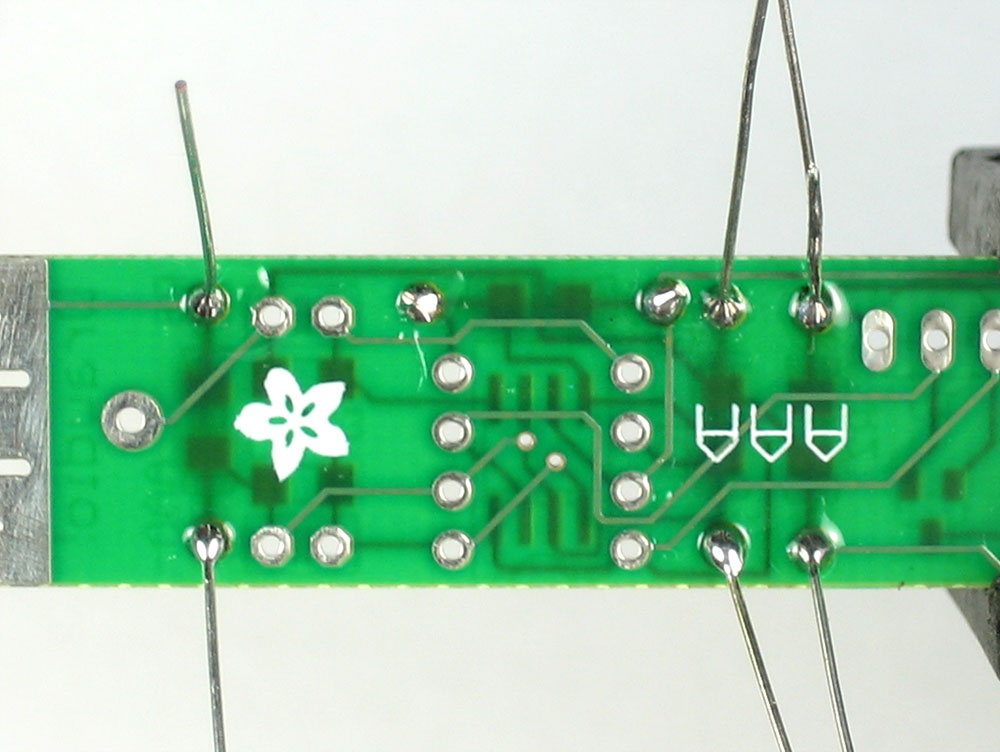
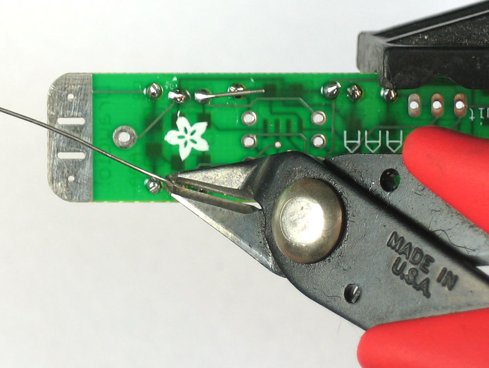
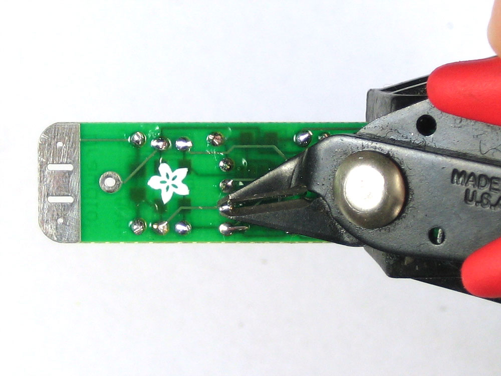
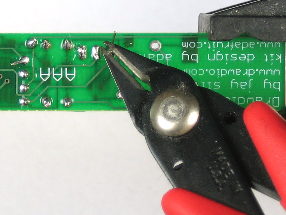
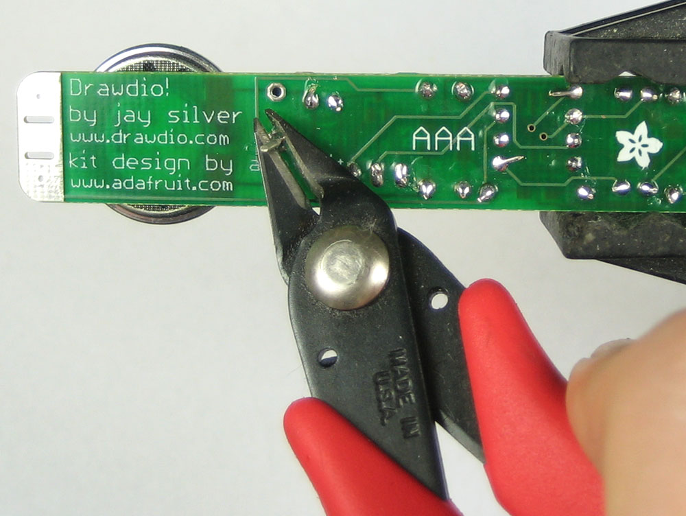
Using your diagonal cutters, cut off the long leads just above the solder joint. |
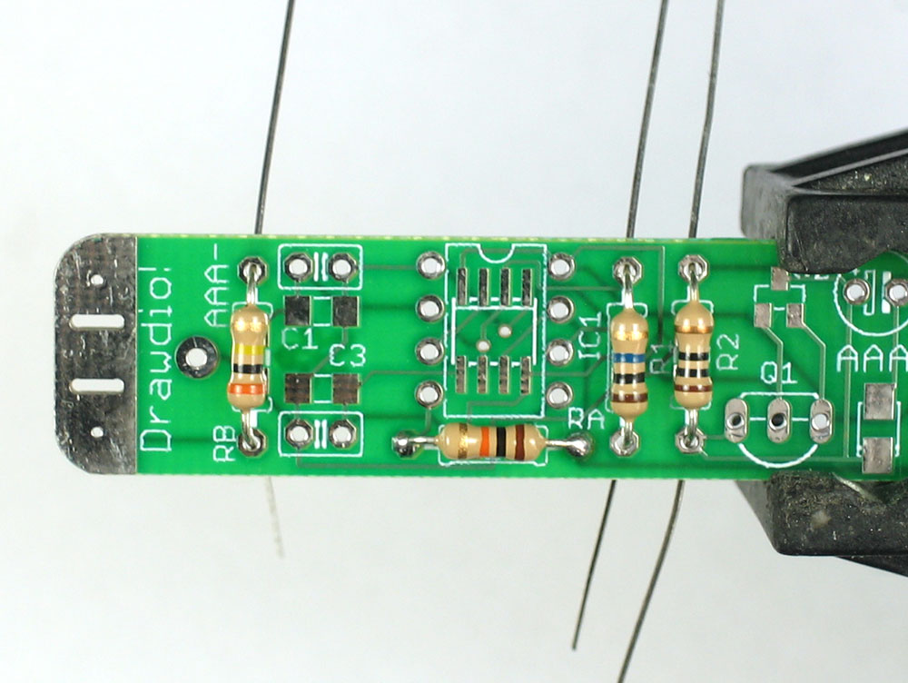 |
Next are the other 3 resistors. Start with the resistor RB. This resistor has a different value, 300K. The stripes are Orange Black Yellow Gold. Place that on the left, next to the RB silkscreen. Then place R1 this is a 10 megaohm resistor! The stripes ae brown black blue gold. Make sure you do not confuse this with R2 which is a 10 ohm resistor. Look under a bright light to tell which one has a blue stripe and which one has a black stripe. If you not sure, a multimeter will help measure the resistance. Finally, place R2 which a 10 ohm resistor. The stripes are brown black black gold. Make sure you do not confuse this with R1 which is a 10 megaohm resistor. Look under a bright light to tell which one has a blue stripe and which one has a black stripe. If you not sure, a multimeter will help measure the resistance. Check again to make sure you did not confuse R1 and R2. Really, you need to look under a good light and a mistake here will be difficult to determine later! |
|
Once you are positive about R1 and R2, solder in these resistors using the same technique you used for the first resistor. |
(oops forgot to take a photo here!)
|
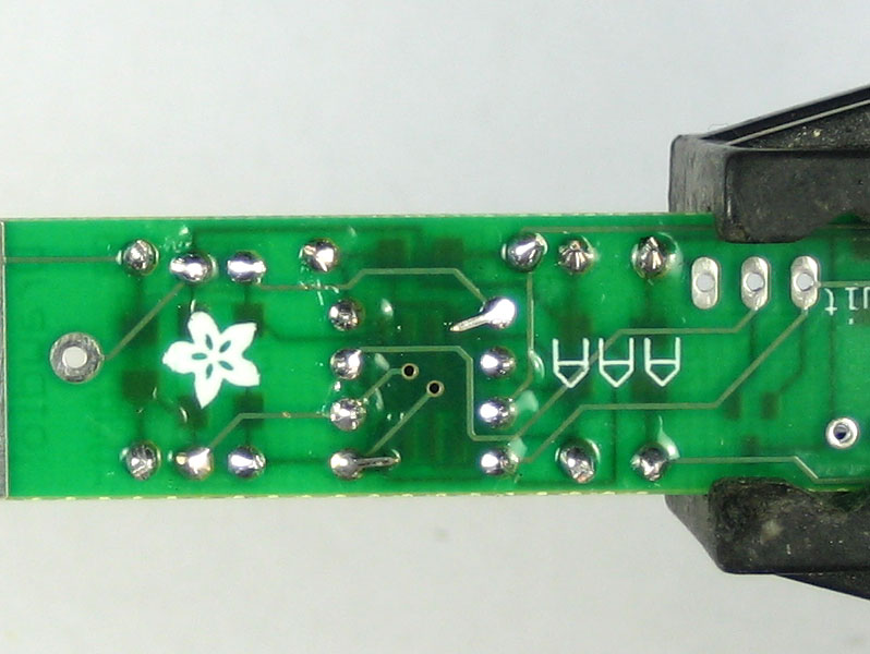
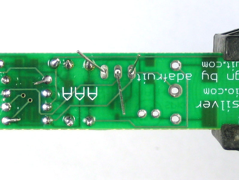
Clip the resistors |
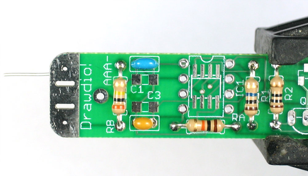 |
Next are the two ceramic capacitors C1 and C3. Ceramic capacitors also have a nice property that they are symmetric/non-polarized. That means they can go in 'either way'. The capacitors are different values so make sure to not mix them up. C3 is a yellow 0.1uF capacitor and has a "104" marking on it. C1 is the blue 680pF capacitor and has a "682" marking on it. Place the capacitors so that the 2 legs (leads) slide thru the two metal holes in the PCB (pads). The capacitor will sit flat against the PCB. |
|
Solder in the capacitors |
|
Clip the leads |
|
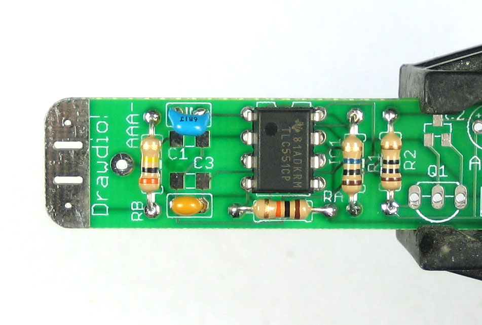
Next is the heart of the kit, a low voltage 555 timer chip. This one is called the TLC551. The important thing to note about the chip is that it is not symmetric. If it is put in wrong it will not work! Its also nearly impossible to fix if the chip goes in wrong so make triple-sure before you solder it in! The silkscreen on the PCB has a little notch in the top. That notch indicates where the top of the chip is. If you look on the chip, there is a circle/dot imprinted in it on one end. There's also a TI logo at that side. Make sure the chip is inserted so that the top of the chip lines up with the silkscreen notch. Check the photo to the left if you're not sure. |
|
Solder in all 8 pins. You might want to use a piece of tape to hold the chip in place, or use a spare finger if you are dexterous. |
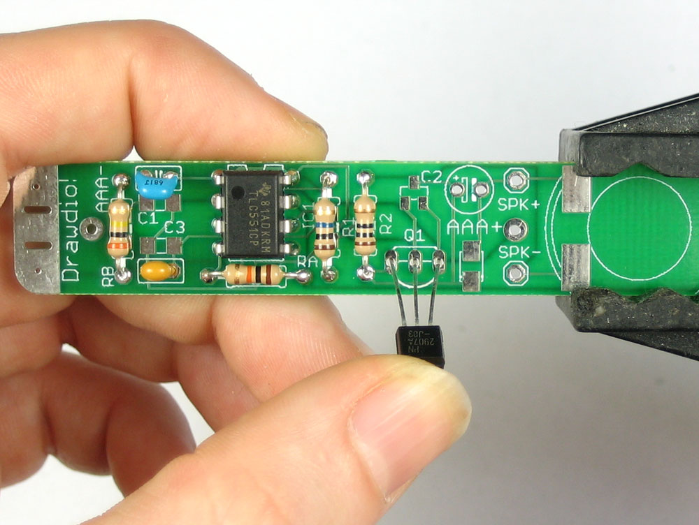 |
Next is the transistor amplifier Q1 which is PNP type Make sure the shape of the transistor matches the silkscreen shape as shown. |
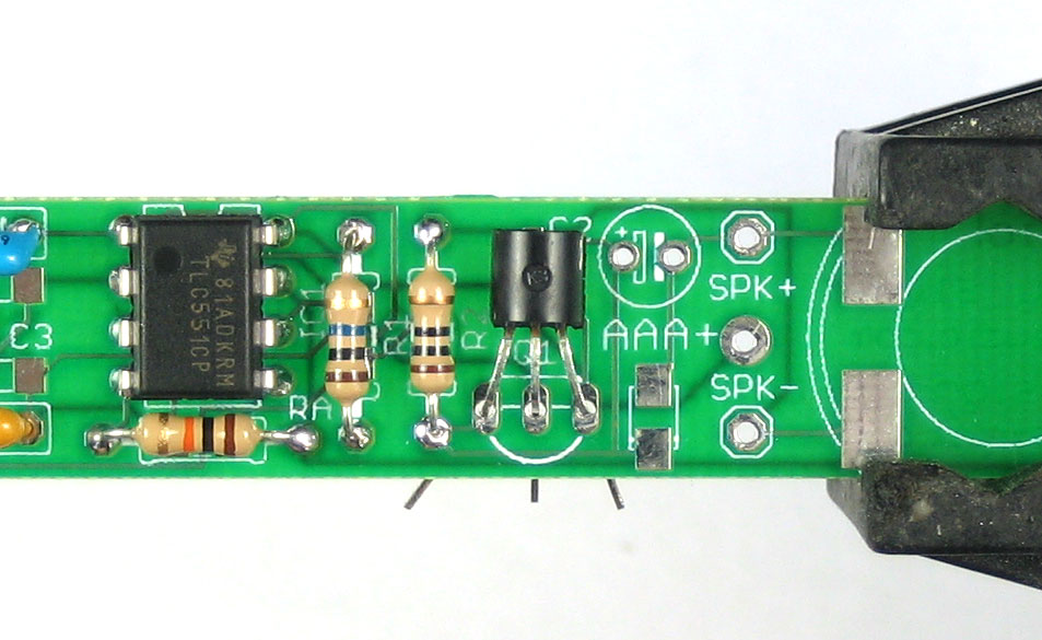 |
Now bend over the transistor so its 'face flat' against the PCB. |
|
Flip over the PCB and solder it in. Then clip the leads |
|
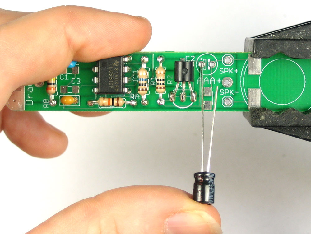
Next is the electrolytic capacitors C2 Electrolytic capacitors are polarized and must be placed correctly or the circuit will not work. The longer lead is the positive (+) one and must go into the pad marked with a + as shown |
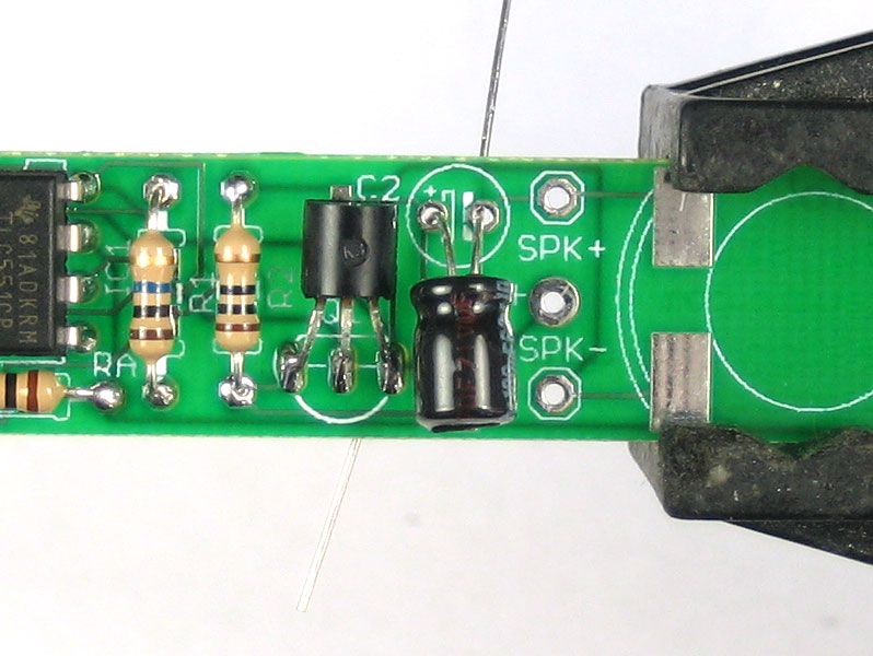 |
Fold the capacitor down so that it lies flat against the PCB. |
|
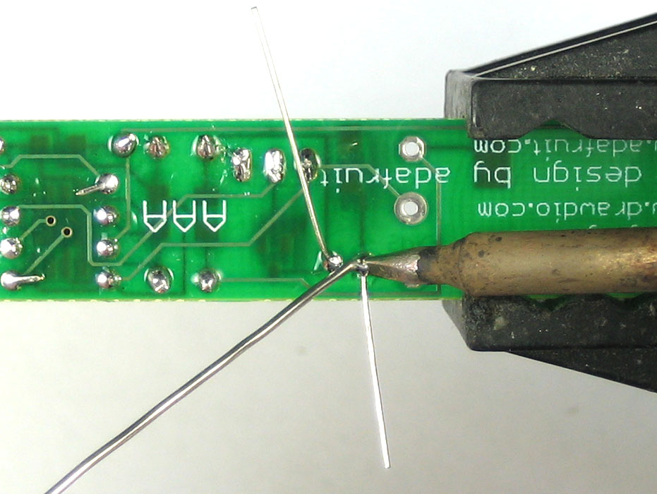
Solder them in, and clip the leads |
|
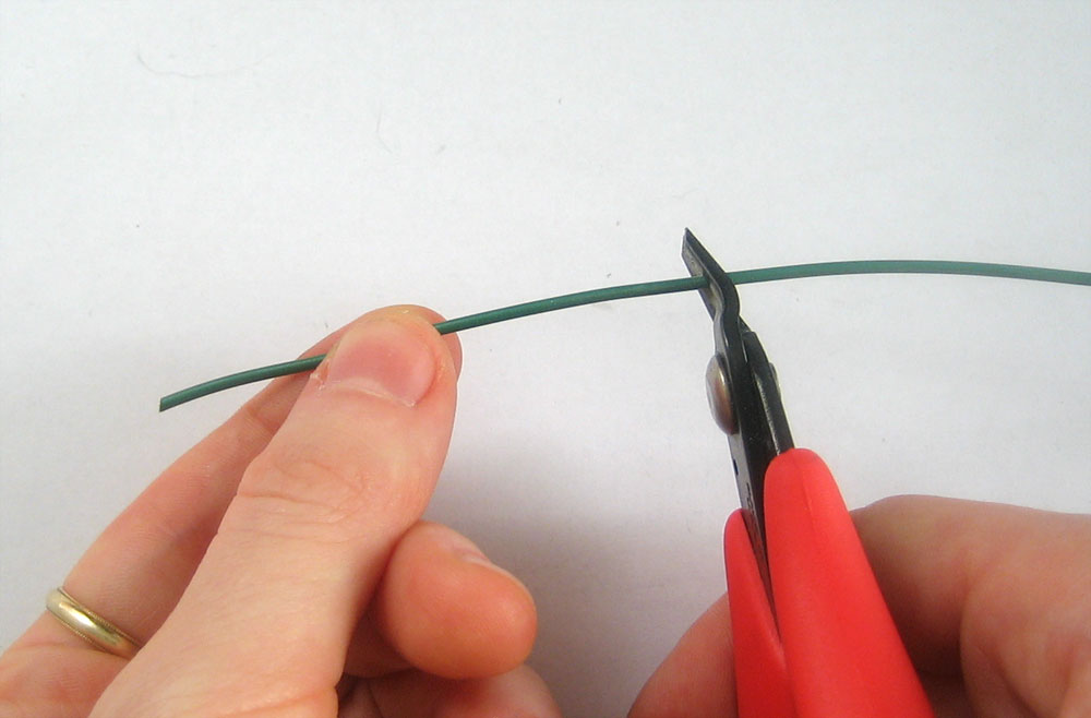
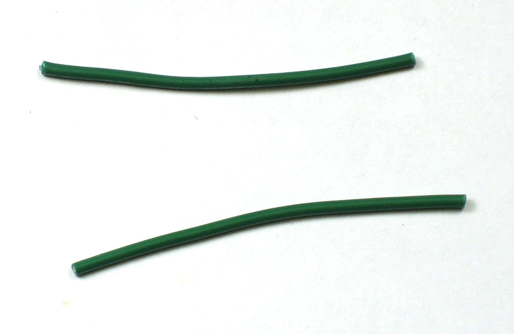
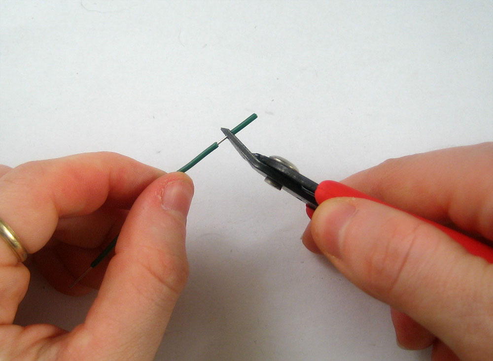
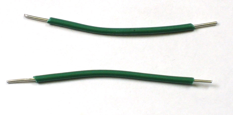
The electronic components are soldered in, next it is time to attach the speaker. There are two ways to go about it. I will show the easier version first which uses wires to attach the speaker. Then I will show the 'more elegant' but difficult version where the speaker is attached directly to the PCB. Use the diagonal cutters to clip off 2 2-3" pieces of wires |
|
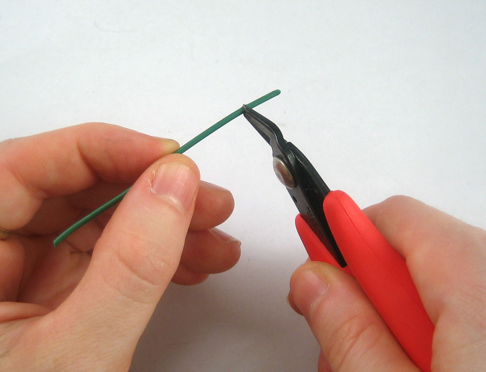
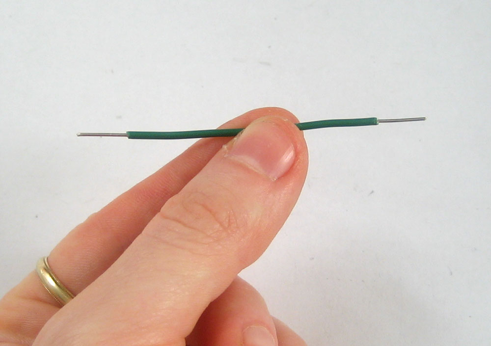
Next, nick the insulation 1/4" from the ends of the wire, and pull it off. If you have 'wire strippers', use them as they are a little easier! |
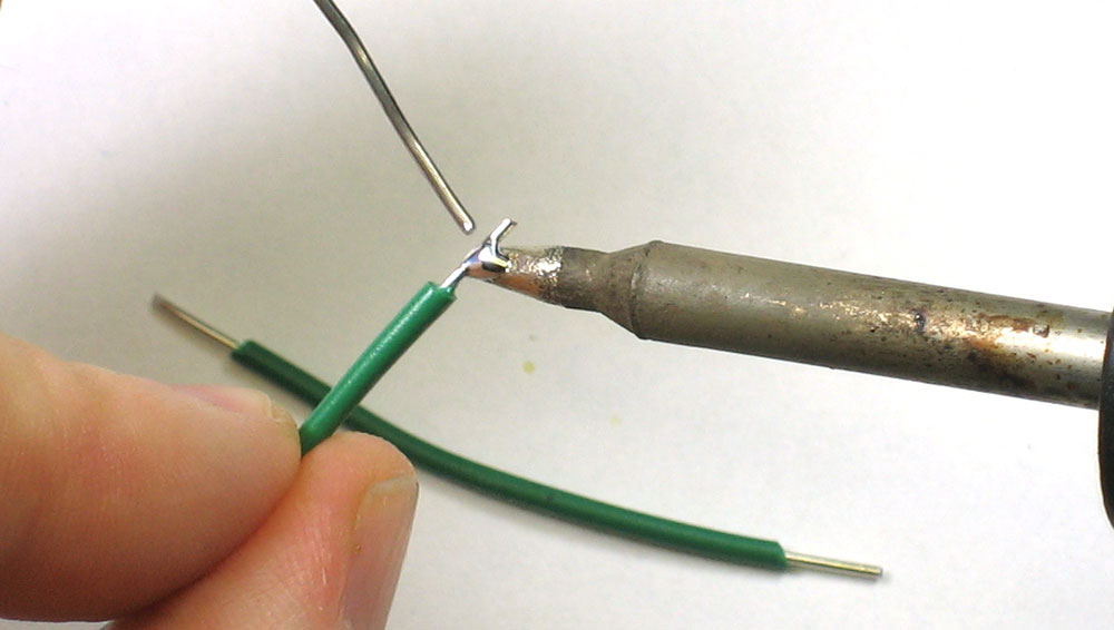 |
Next, it is a good idea to tin the ends of the wires. Its a little tricky because it requires holding three things. However, if you have a 'third hand tool' or a vise, you can use that to hold the wire while you heat up the stripped end and coat it with a little bit of solder. This will make it easier to connect to the speaker. |
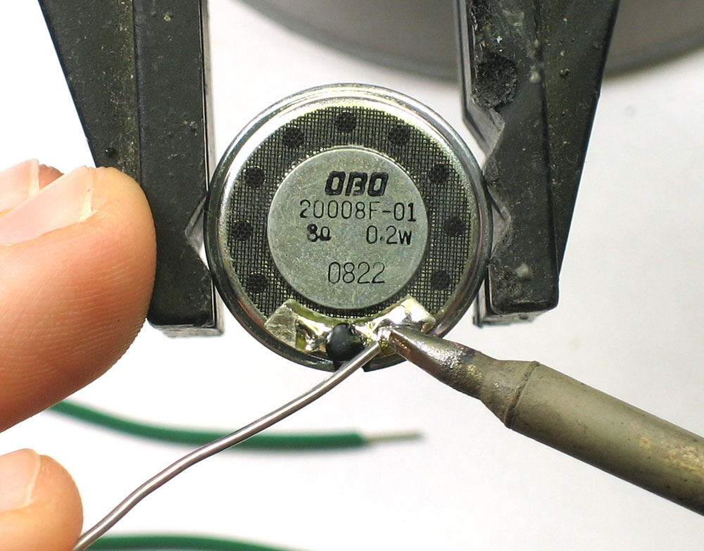 |
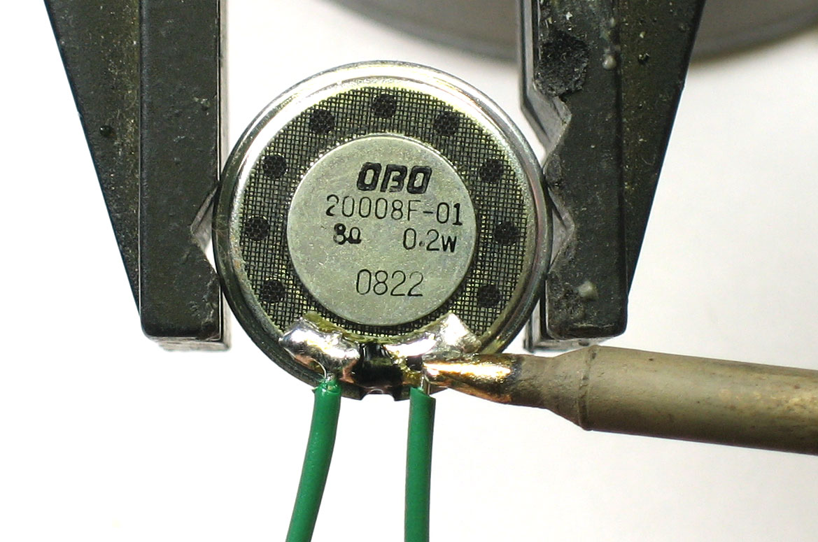
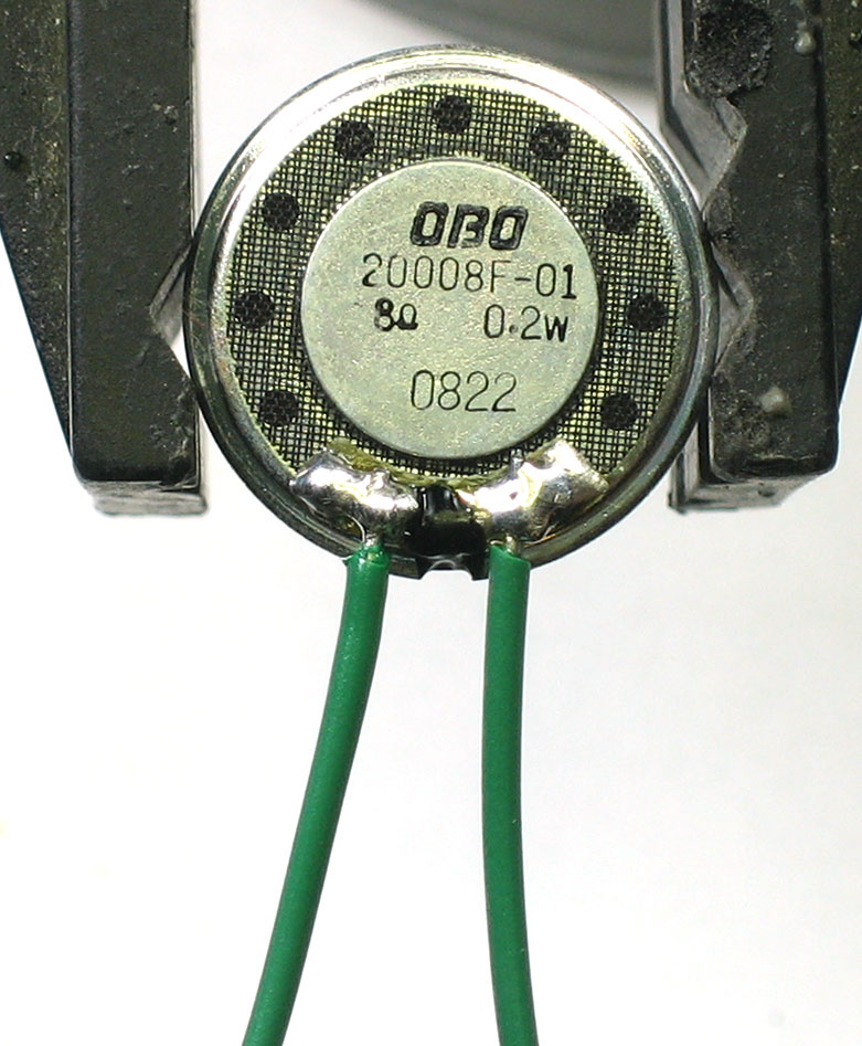
On the opposite side of the speaker there are two solder tabs. Heat them up and add a little more solder. Don't spend too much time on them (more than 3-4 seconds) since the speaker is made of plastic and if it heats up too much it will melt! |
|
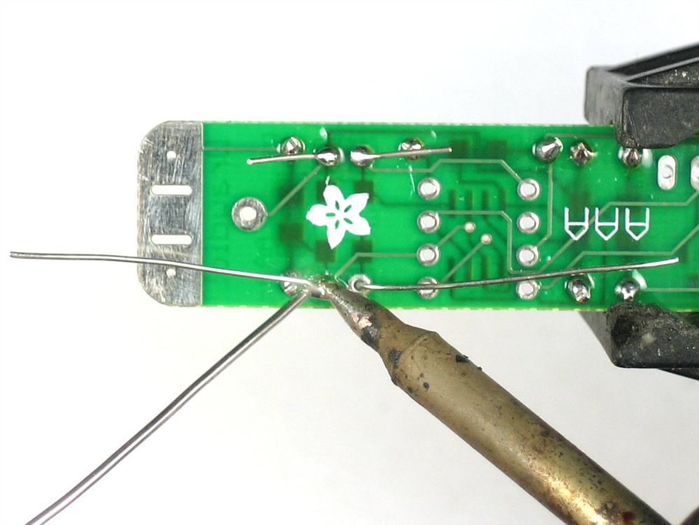
Next, warm up the tabs and slide the tinned ends of wire into the melted solder pool. Then remove the iron and wait a few seconds, the solder pool will cool with the wire in place. Do the same for the other pad |
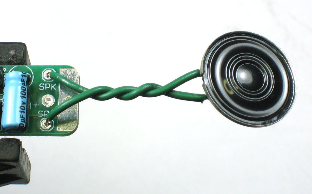 |
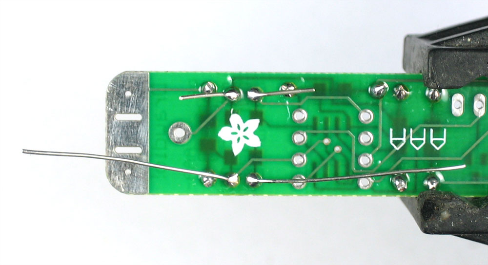
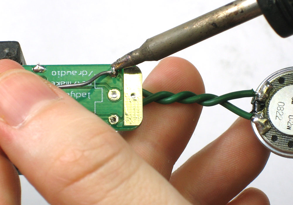
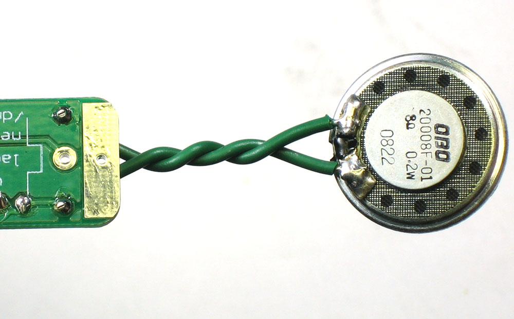
Twist the wires, this will reduce the strain on the solder joints when bending. Put the end of each wire into the two PCB holea marked SPK+ and SPK-. Don't solder into the hole in the middle which is for the battery. The speaker is 'symmetric' so it doesnt matter which wire goes in which hole. |
|
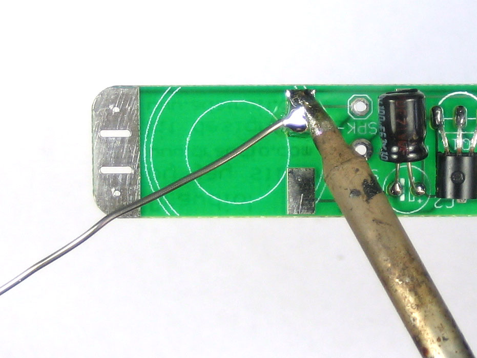
Solder the wires into place. |
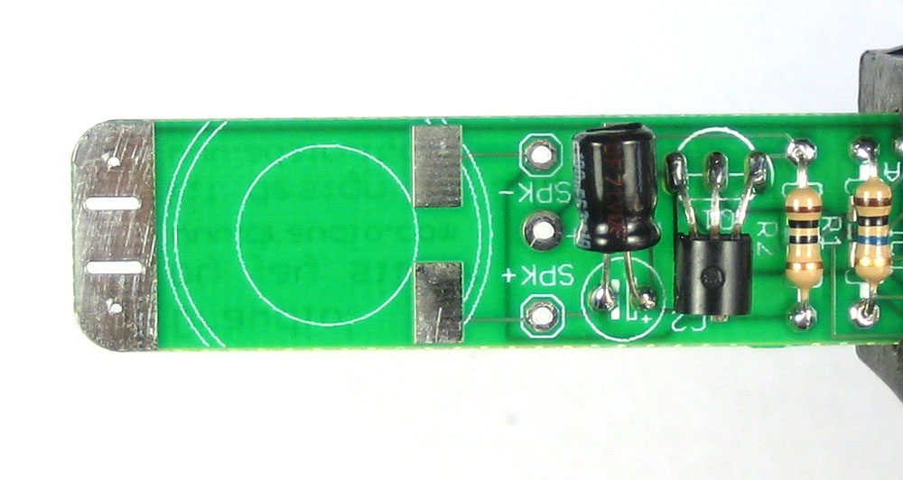 |
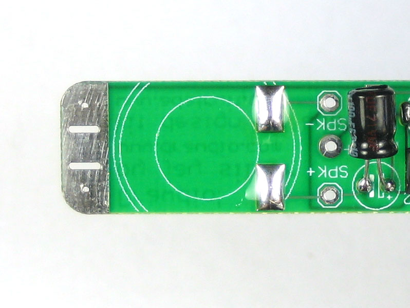
This is the more challenging way to attach the speaker but is a little more 'elegant' looking Prepare by finding the two big pads for the speaker |
|
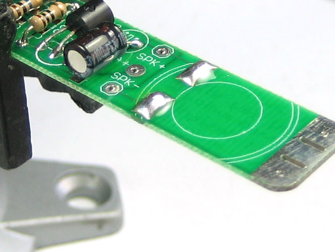
Now melt a lot of solder onto the two pads |
 |
Tape or otherwise hold the speaker tabs against the blobs |
|
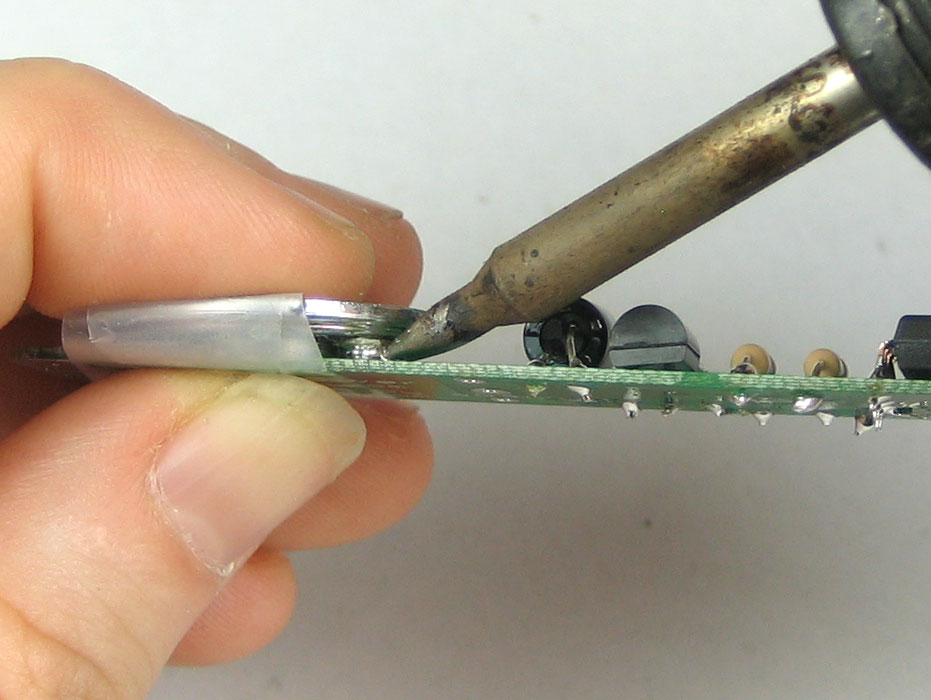
Now use the tip of your iron to quickly remelt the blobs so that they flow onto the speaker tabs |
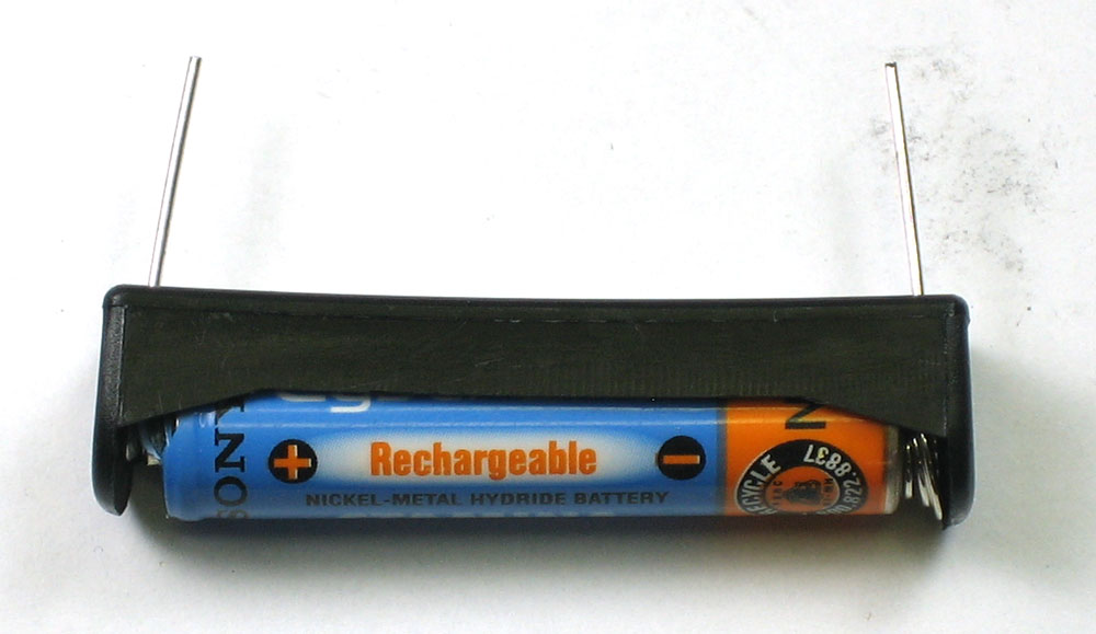 |
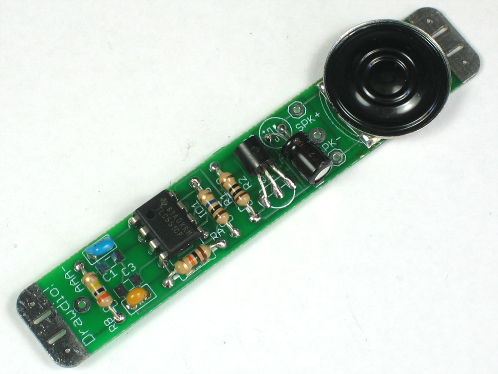
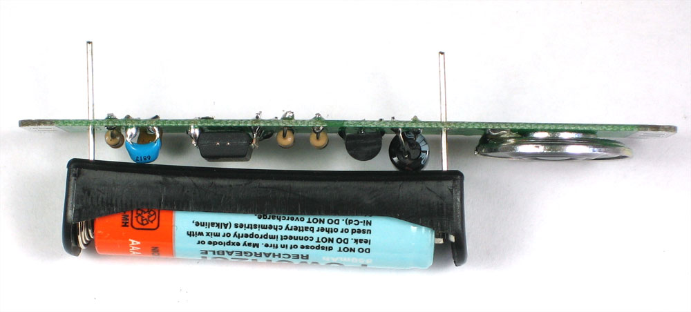
OK no matter which way you attached the speaker we will move to the next step Now its time to do a quick test before finishing up. Place a AAA battery in the holder |
|
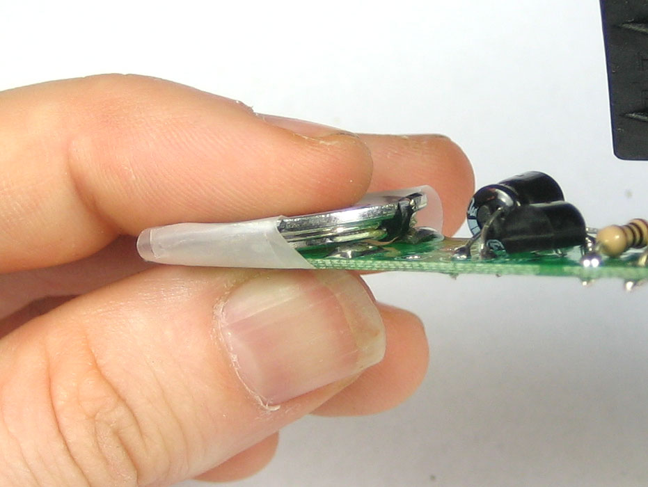
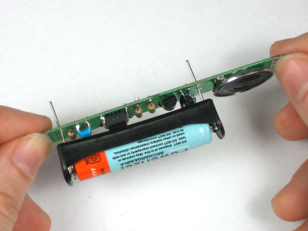
Slide the battery holder into the PCB (but do not solder it in). Make sure that the battery is aligned correctly. Putting in the battery backwards shouldn't damage the circuit but its still not a good idea so try to get it right the first time. The back of the PCB has a silkscreen to help determine which way the battery goes in. With the battery holder in place (but, again, not soldered in) touch both sides of the PCB. A squeaking noise should come out of the speaker! As you press harder/softer, the pitch will change. That indicates the circuit is working. If its not making noise, try: |
|
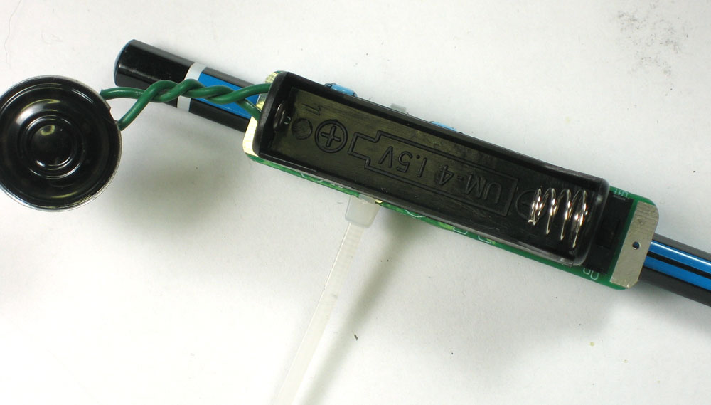
Once you are tested and happy, its time to finish up! Remove the battery and place the battery holder on top of the components, as shown. Bend the leads a little so that it sits as tight as possible. Solder in the battery holder, and clip the leads short. |
|
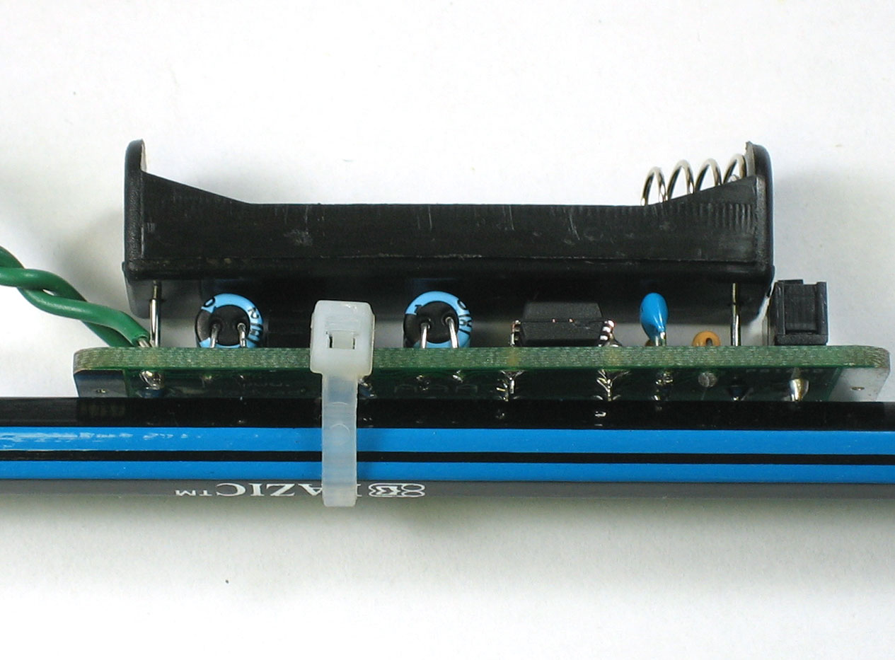
Next you can mount the PCB to your pencil. Place the PCB on the flat side of a pencil, and thread the zip tie through as shown and tighten it. You'll want it about an inch or less from the top of the pencil. The higher it is the more pencil you'll have to sharpen but it may be a little more unbalanced. |
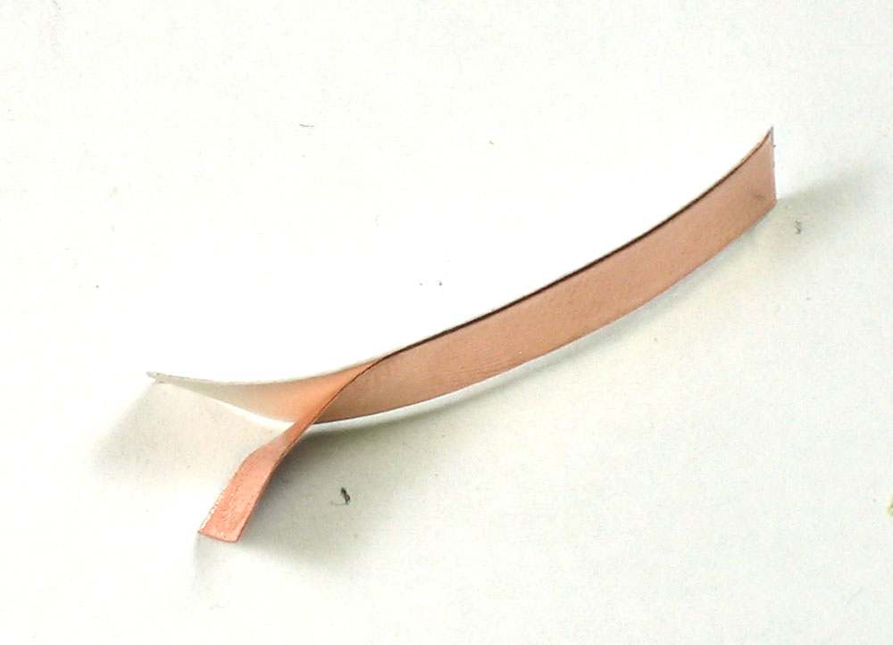 |
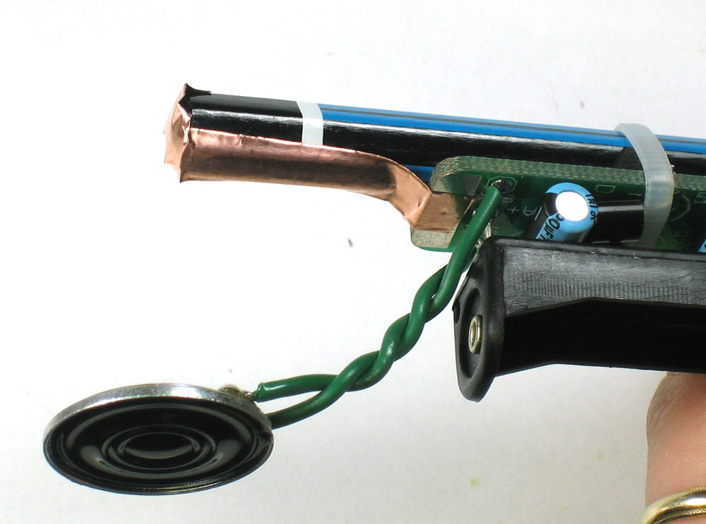
Next cut a 1.5" piece of copper tape using the diagonal cutters. Don't use scissors as the metal tape can damage them. peel off the paper backing. The copper tape is conductive, sticky and flexible which makes it perfect for wrapping the pencil |
|
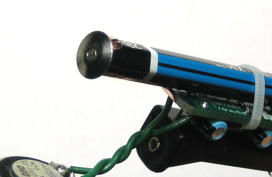
Wrap the tape along the top of the pencil so that the beginning is at the silver metal tab on the PCB, as shown Then take the thumbtack and gently push it into the end of the pencil. You might have to twist it back & forth a little to get it all the way in. The thumbtack will grip the copper tape and also make contact with the graphite in the middle of the pencil to make the first half of the drawing sensor |
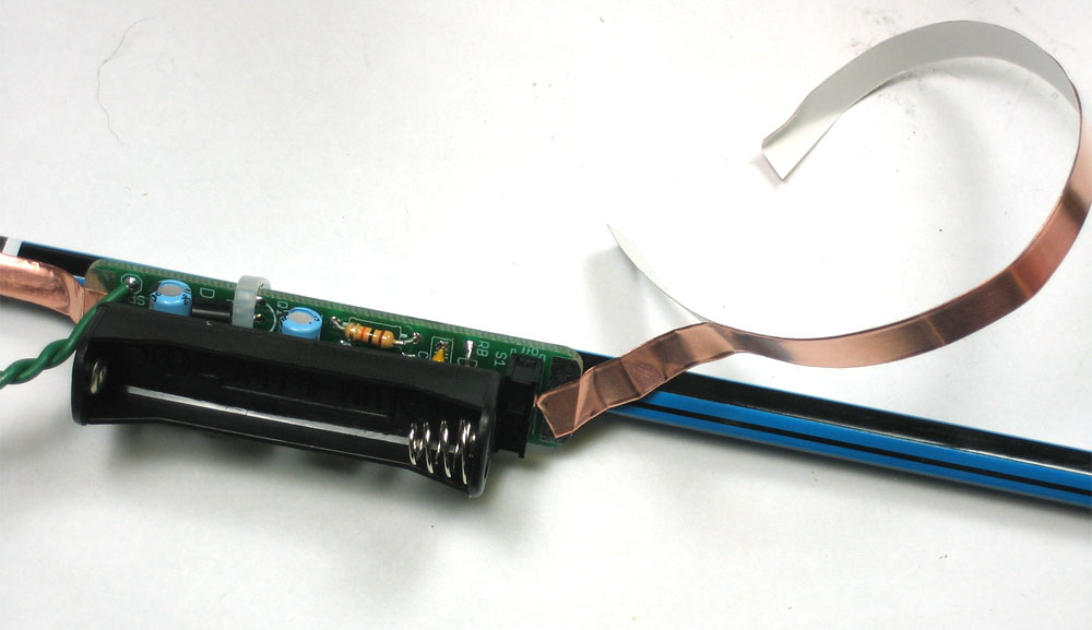 |
Next take 3 or 4" of copper tape and start wrapping around the bottom of the pencil, starting with the silver tab on the PCB and ending an inch before the end of the pencil. This will make contact with your hand and provide the second half of the sensor. |
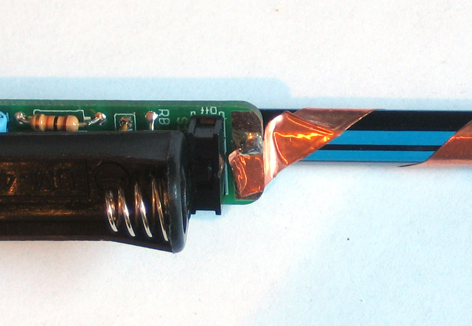 |
Solder the copper tape to the tab directly as shown |
|
Finally, insert a battery into the kit. Then grip the pencil with one hand and touch the point of the pencil to your other hand. You will be able to hear the drawdio make noise! Next up, see the user manual for ideas on how to make the most of your drawdio |