|
Velocity estimation is made possible by a cool feature of the HostMot2 firmware: The FPGA synthesizes a configurable-frequency "timestamp clock" by dividing ClockLow by the value in the Quadrature Counter Timestamp Divider Register. ClockLow is 33 MHz on the PCI cards and 50 MHz on the 7i43. The current value of the Timestamp Clock can be read from the 16-bit Timestamp Count (TSC) register. When a quadrature counter instance in the HostMot2 FPGA detects a transition in its input Gray code, it increments the count and latches both the (16-bit) count and the 16 bits of the timestamp clock into the Counter Register. |
|
|
Some Random Notes:
|
|
|
The velocity estimator used by the driver is similar to one described by David Auslander in a paper titled " Vehicle-based Control Computer Systems" (UCB ITS PRR 95 3). |
|
Algorithm notes:
|
|
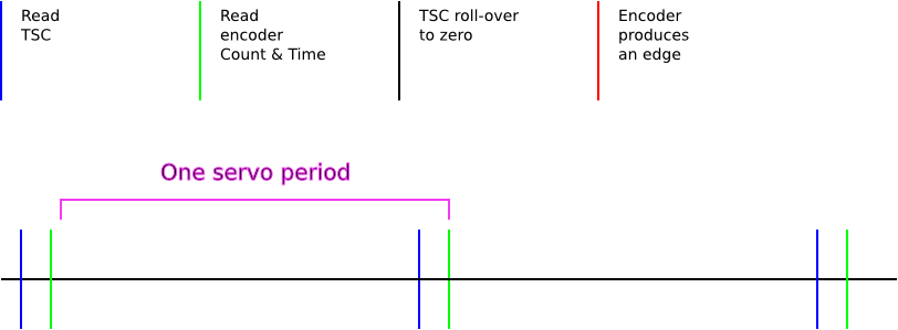
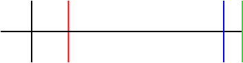
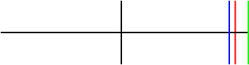
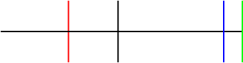
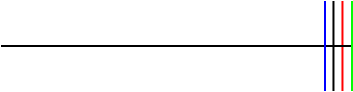
Legend: |
|
|
|
1. No encoder edge |
2. Encoder edge before TSC read |
3. Encoder edge between TSC read and C&T read |
|
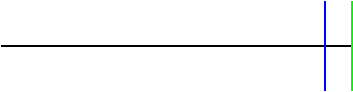
A. No rollover |
|
|

|
|
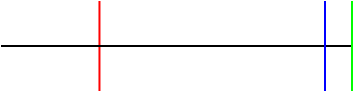
B. Rollover happens first |
|
|
|
|
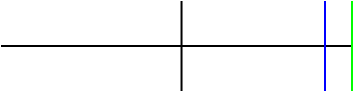
C. Rollover happens second |

|
|
|
|
D. Rollover happens third |
There is no Case D1 |
|

|
|
Case A1: No rollover, no encoder edge. |
|
MM = Stopped |
Nothing to do. |
MM = Moving |
TI is TSC. Do rollover check. We detect rollover here if PTI was pre-rollover, which means the previous time through the loop was case C1 or C2 or D2 or D3. dT is ((TI - OT) + (R * 2^16)). dT > Horizon? If so V = 0 and MM = Stopped. We'll wait a little longer, Use UBVE. PTI gets the value of TI (TSC). |
|
Case A2: No rollover, encoder edge before TSC read. |
|
MM = Stopped |
Old Datapoint = new datapoint R = 0 MM = Moving PTI = T |
MM = Moving |
TI = T, do rollover detection. We detect rollover here if PTI was pre-rollover. Use RTVE. OD = new datapoint PTI = TI (= T) |
|
Case A3: No rollover, encoder edge between TSC read and C&T read. |
|
|
Identical to A2. |
|
|
Case B1: Rollover happens first, no encoder edge |
|
MM = Stopped |
Nothing happens. |
MM = Moving |
TI = TSC. Check for rollover. Rollover detected, because PTI is either T or TSC from the previous servo loop, which ended just before the rollover. Compute dT, check for Stop. Use UBVE. PTI = TI (= TSC) |
|
Case B2: Rollover happens first, encoder edge before TSC read. |
|
MM = Stopped |
Identical to A2. |
MM = Moving |
TI = T, check for rollover, rollover detected, because PTI is either T or TSC from the previous servo loop, which ended just before the rollover. RTVE PTI = TI (= T) |
|
Case B3: Rollover happens first, encoder edge between TSC read and C&T read |
|
|
Identical to B2 |
|
|
Case C1: Rollover happens second, no encoder edge |
|
MM = Stopped |
Nothing to do. |
MM = Moving |
TI = TSC, check for rollover, no rollover detected (because TSC is just before the rollover). UBVE PTI = TI (= TSC) |
|
Case C2: Rollover happens second, encoder edge before TSC read. |
|
MM = Stopped |
Like A2. |
MM = Moving |
TI = T, check for rollover, no rollover detected (because T is just before the rollover). RTVE PTI = TI (= T) |
|
Case C3: Rollover happens second, encoder edge between TSC read and C&T read |
|
|
Identical to B2 and B3. |
|
|
Case D2: Rollover happens third, encoder edge before TSC read. |
|
MM = Stopped |
Like A2. |
MM = Moving |
TI = T, check for rollover, no rollover detected (because T is just before the rollover). RTVE PTI = TI (= T) |
|
Case D3: Rollover happens third, encoder edge between TSC read and C&T read. |
|
|
Identical to D2. |
|